Leak Stereo 20 Restoration
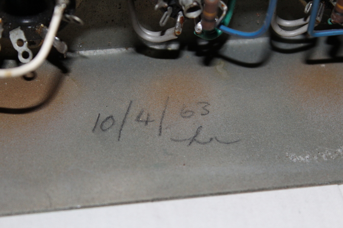
About 10 years ago, my Dad was given a Leak Stereo 20 amplifier from my uncle, who I think was given it from someone else after it was removed from some weird wooden stereo console. The amplifier is dated 1963, but probably hasn't been used for around 25 years at this point.
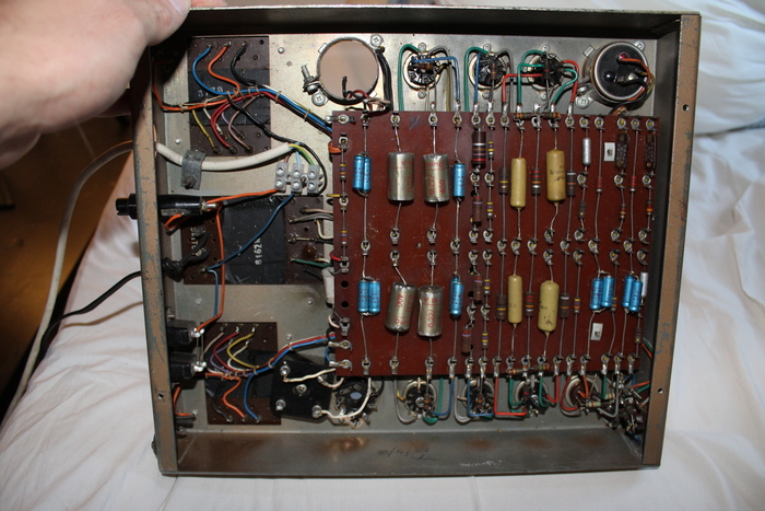
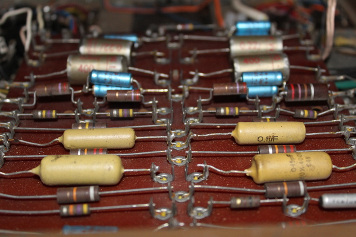
Last year, almost exactly a year ago actually, I ordered a new set of tubes for the amplifier, but never got round to repairing it. Here are a few photos of the status of it when I got it.
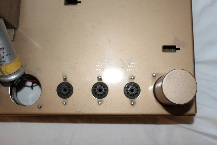
As you can see, it's clearly had some work done to it before. The GZ34 rectifier socket has been disconnected, and in it's place is a solid state rectifier. There are a bunch of capacitors which have likely been replaced too, but not all of them. The work is a bit scruffy in general. capacitor is sort of hanging out because it was the wrong size.
This weekend I decided to figure out what I needed to buy to get the amplifier in working order. As I said earlier, I had already bought a full set of tubes for the amplifier. I decided to order the following from Farnell.
| Caps | Value | Replacement | Part No | Qty |
|---|---|---|---|---|
| C10/C11 & C12/C13 | 32uF / 32uF, 400V | PANASONIC - Electrolytic Capacitor, 47 µF, 400 V | EEUEE2G470S | 5 |
| C1L/R | 1nF, 400V | Not replaced yet | ||
| C2L/R | 50uF, 12V, electrolytic | VISHAY - Electrolytic Capacitor, 47 µF, 25 V, | MAL203036479E3 | 10 |
| C3L/R | 0.1uF, 350V | VISHAY - DC Film Capacitor, 0.1 µF, 400 V, PET | MKT1813410405G | 5 |
| C4L/R & C6L/R | 0.25uF, 350V | VISHAY - DC Film Capacitor, 0.22 µF, 400 V, PET | MKT1813422405G | 5 |
| C5L/R | 0.02uF, 350V | Same as C3 | – | – |
| C7L/R & C8L/R | 50uF, 25V | Same as C2 | – | – |
| C9L/R | 200pF | KEMET - Multilayer Ceramic Capacitor, 220 pF, 100 V | C410C221J1G5TA7200 | 10 |
I did not end up replacing C1L/R because I couldn't find an appropriate capacitor. I'm not convinced these capacitors are required and may end up removing them. They are in parallel with a resistor on the output. The GZ34 rectifier socket was rewired after I removed the solid state rectifier.
After installing all of the new capacitors as shown in the schematic, I powered it up. Much to my surprise, the tubes went into emission and I started to hear Beirut. But shortly after I started to notice a bad smell… R20 started smoking, so I quickly disconnected it. After messing around for about an hour, checking all the resistors were ok, it occured to me that C10 and C11 must be backwards. I thought this was weird when I was wiring them up originally, but decided to follow the schematic anyway. After correcting that the amplifier worked great… for a few minutes.
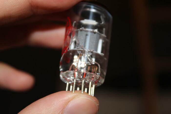
The left channel cut out, so I turned the amplifier off. Everything underneath looked fine so I inspected the tubes. V2L had a small crack in it. Hopefully just a manufacturing fault as the heater voltage is fine. I'll go into town and pick up a few more 12AX7 tubes. Here's a photo of the cracked tube:
All of the tubes were ordered from jjtubes.eu. In total I ordered:
| Tube | Quantity |
|---|---|
| EL84 | 4 Matched |
| ECC83S / 12AX7 | 3 |
| GZ34 | 1 |
There are still a few things I want/need to do:
- Replace the speaker terminals on the back with banana jacks. The current connectors are literally screws.
- The amplifier has two power sockets on the rear side. I find this quite unsafe and would like to disconnect them. Perhaps in that space I could fit a male IEC power socket.
- The power lead is too short, although if I do the previously mentioned this, this will not be an issue.
- I'd like to paint the unit. I'm thinking either dark matte blue or a medium matte grey.
- There are two holes from the old large filter capacitors. I don't have one of the original capacitors, so I'm thinking about covering these holes with a small square of steel.
- After R20 went smokey, I replaced it with a few other resistors in parallel (distribute the current). This is pretty messy and I'd like to replace it with a single resistor. I suspect it'll need to be rated for 2-3 watts.
I'll post some more photos of the amplifier in it's restored condition once I'm happy with it. For now, here's just one, showing the tubes glowing.
Here's the circuit diagram just in case it goes missing from the web - notice the unusual orientation of C10 and C11, top left.
Related posts:


Wanting to leave a comment?
Comments and feedback are welcome by email (aaron@nospam-aaronsplace.co.uk).