VT220 Debugging (again...)
Documented below is a tale of hope and disappointment. My original hypothesis of a faulty secondary winding diode in the flyback transformer turned out not to be true. After several hours of investigation, the answer was just as disappointing.
—
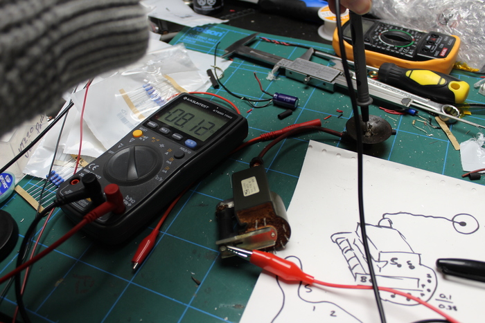
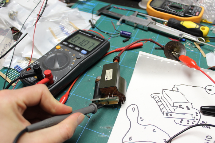
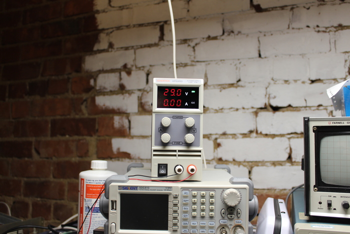
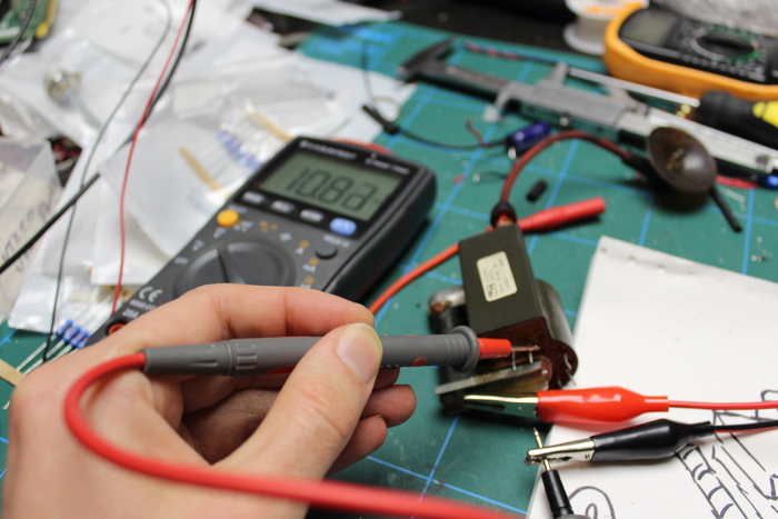
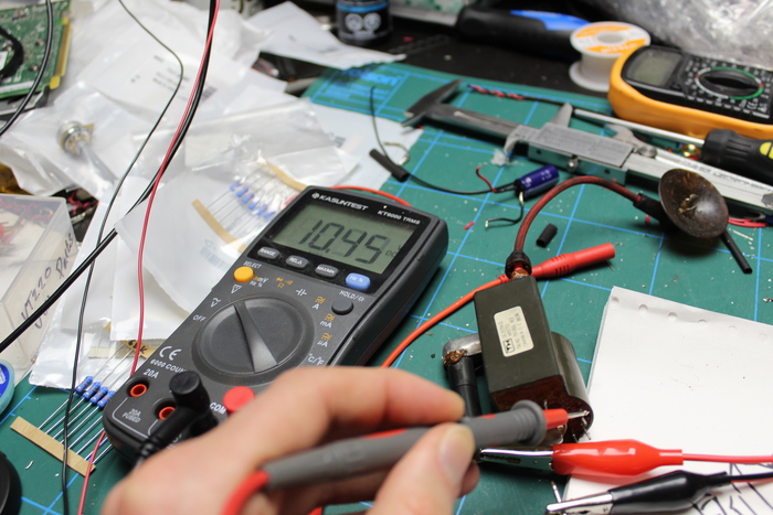
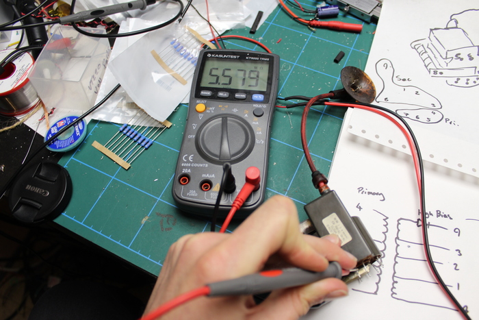
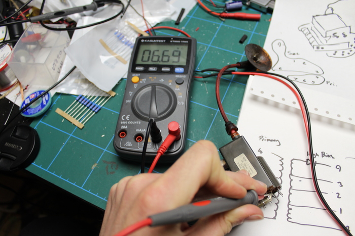
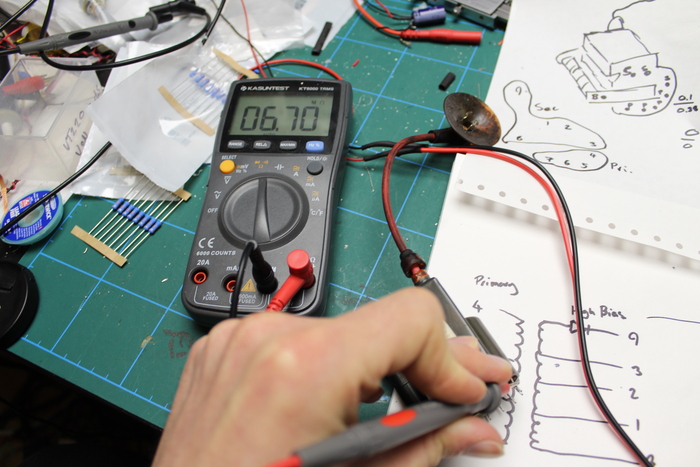
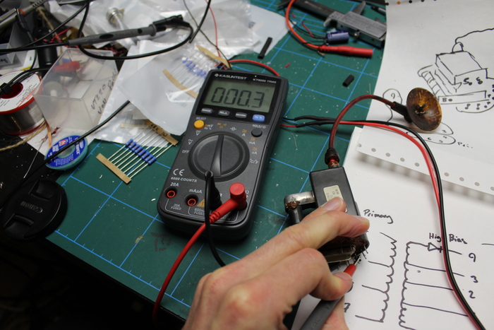
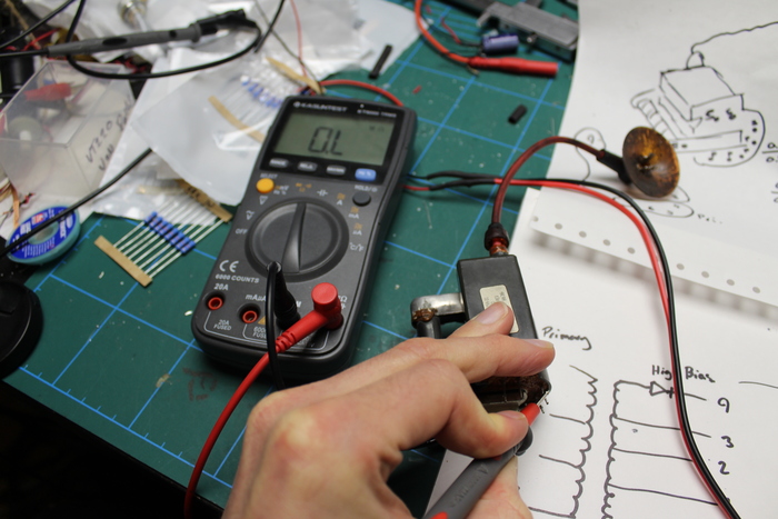
The VT220 flyback transformer has an internal diode which I have suspected being bad for a while now. Tonight I decided to test it. With 29v input I get an 8v forward and 0.1v backwards, so it does appear to be operating like a diode.
Between the base of the secondary winding and the three next pins, there is some voltage drop although I'm not entirely sure how these are wired up since it doesn't appear to be sequential.
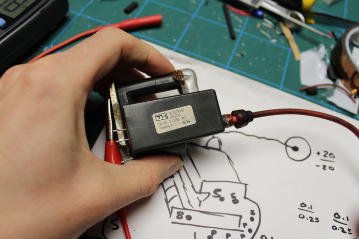
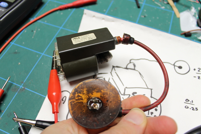
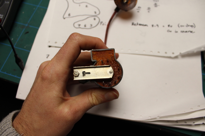
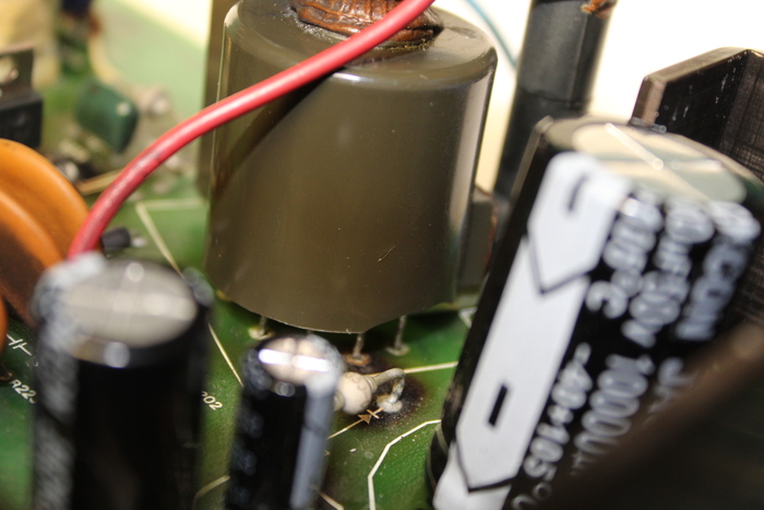
Here's just a couple of photos of the transformer.
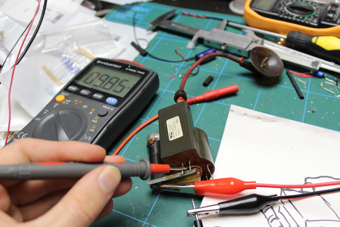
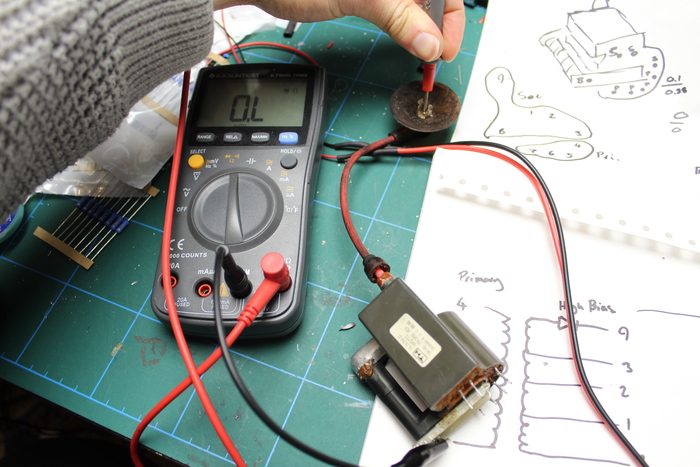
Checking the resistances across the secondary. They all seem to be in the megaohms and it was fluctuating a bit, so I definitely suspect there being a capacitor in here too.
A quick check through the primary windings confirms that these are either shorted (lol) or completely fine. 0.3 ohm does seem quite low.
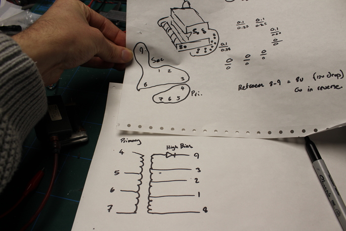
Here's a view from the bottom side along with a couple of diagrams approximating the internals of the transformer:
There were many different versions of the VT220 sold, and I believe these had one of two different flyback transformers. The schematics I have from bitsavers do not seem to match up with the terminal I have exactly, so we can assume the internals of the "other model" of VT220 have a flyback like so:

So we have confirmed the existence of this diode and that it appears to be working. I'll have to trace the circuit board to see the other bins, although I appear to have an additional pin - perhaps it wasn't actually used on the version I have.
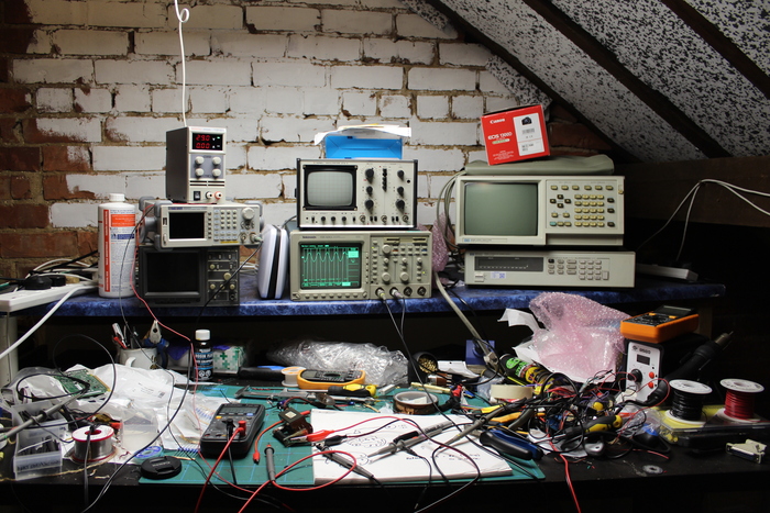
Bonus equipment photo:
—
<2020-04-09 Thu 13:45> Thinking…
So here is the current state.
- The logic of the terminal appears to be fine.
- Powering on the terminal with Q202 switching transistor installed causes it to hiccup. Something is pulling the power supply to ground.
- Having removed Q202 we can be sure that the input to this transistor is fine - we have a nice 14KHz input signal, which is 5v pk-to-pk unloaded.
I'll also dump a larger schematic below showing more of the circuit than the one included above. I've highlighted the 12V rail with red and ground with green.
Ok, I am struggling to understand all of this a bit, so I'm going to try and walk through this step by step.
- Pin 8 of the flyback transformer is attached to a 12V DC rail via a capacitor (C215) and a resistor (R218).
- The switching transistor (Q202) is switched at 14KHz. When this transistor is in its on state, it pulls pin 6 of the flyback transformer to ground.
There are several potential paths this 12V rail could take to ground.
- Through the capacitor C214, if it were faulty.
- Through pin 7 of the FBT, if D201 and C214 were faulty.
- Through pin 5 of the FBT, if D200 or C213 were faulty.
- Through pin 6 of the FBT, if C106 was faulty.
- Through pin 6 of the FBT, if Q202 is on or faulty.
Given that the terminal powers on when Q202 is removed, we can safely eliminate the first four of these scenarios. (Can we call this a differential diagnosis? We're doing a DDX! I feel like House, M.D.). I have changed this transistor last time I looked at the terminal, but let's assume it is dead. What would cause this transistor to die?
—
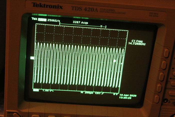
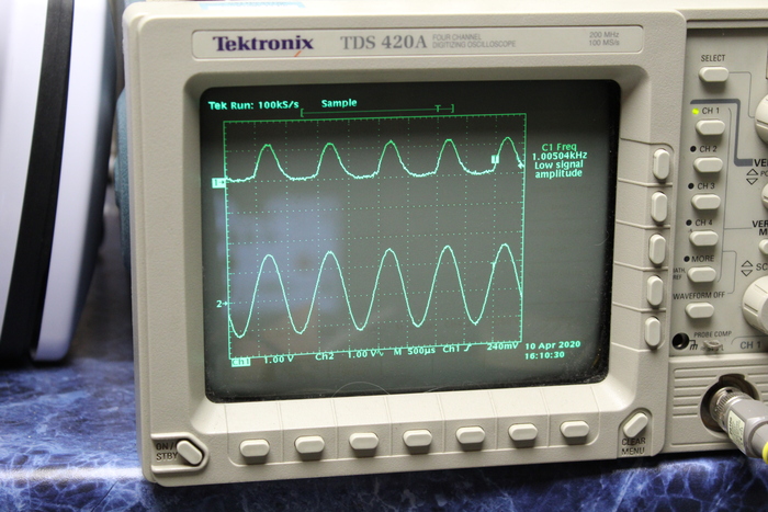
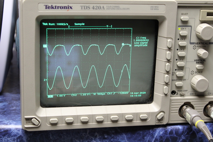
<2020-04-09 Thu 16:47> The End? Well I think we have our answer. Q202 actually seems fine. I also performed some tests on the diodes, and they seem okay but they are slightly sloppy. For reference, this is what a good diode looks like with a sine wave going through it - forwards and reverse:
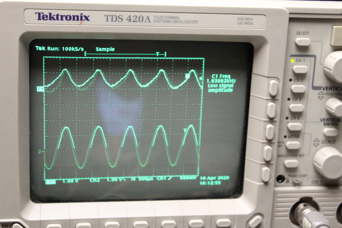
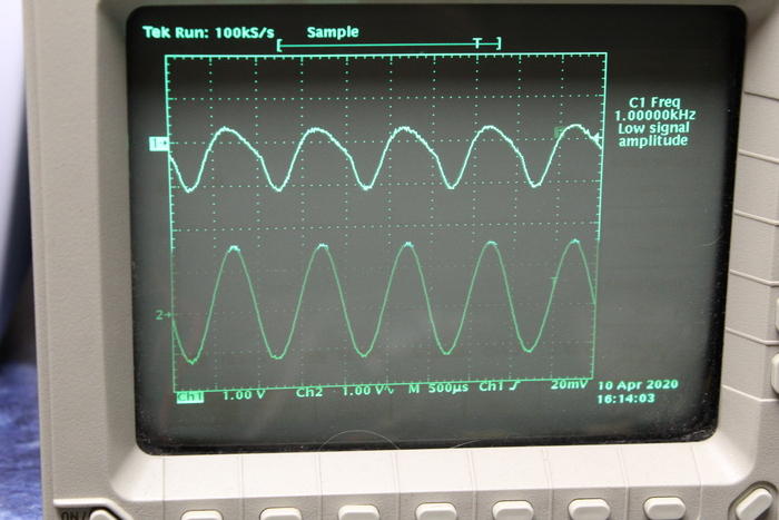
Here's what these diodes look like:
So yeah, they're diodes alright. Really sloppy diodes.
In the first part of this post, I mentioned that the primary winding has a very low resistance of 0.3 ohms. Well, Q202 provides a path to ground when switched on, from the 12v rail through a chunky 3W resistor. I've come to the conclusion the primary winding has shorted. Very disappointing.
—
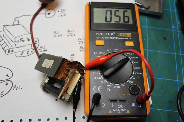
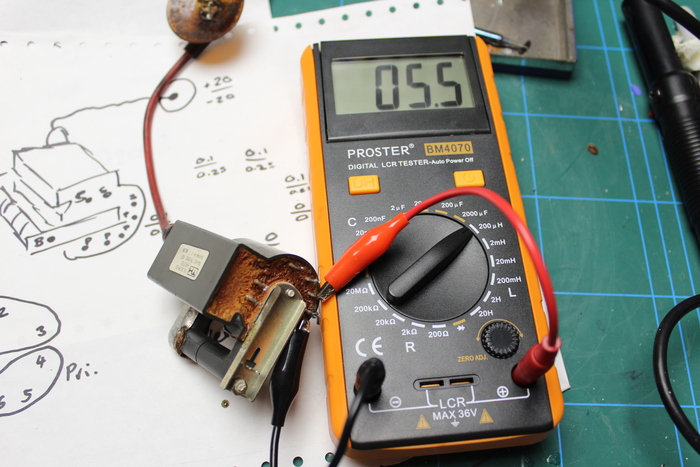
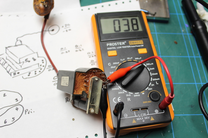
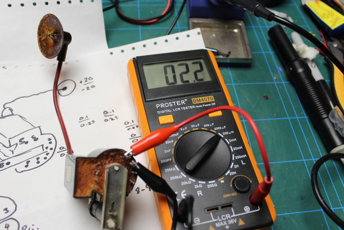
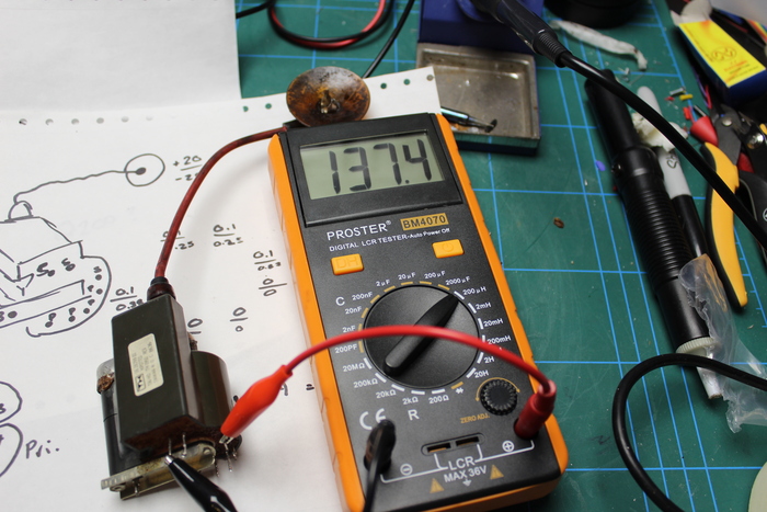
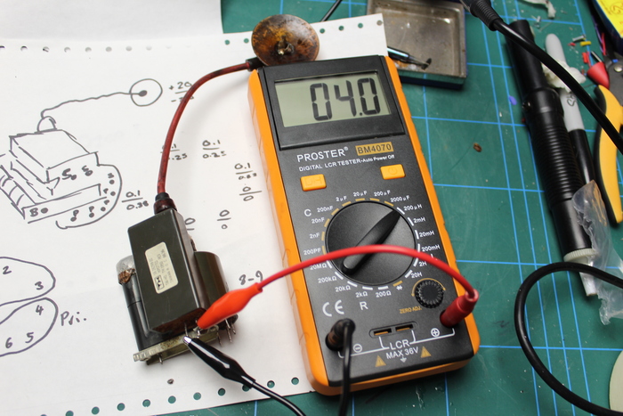
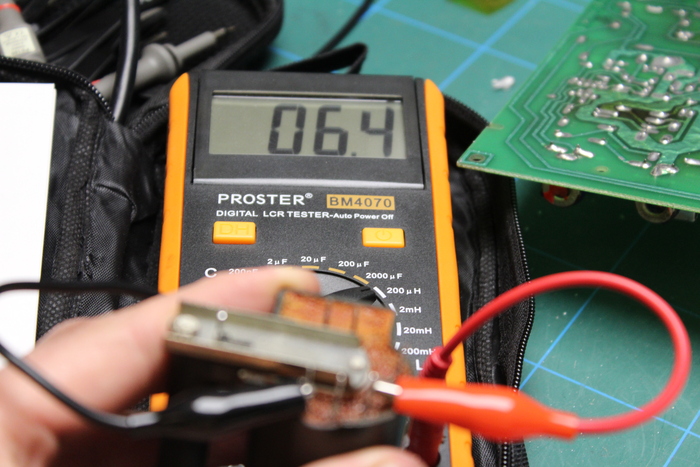
<2020-04-09 Thu 19:29> Inductance I suppose we can go a step further and check the inductance of the flyback transformer's windings. First, the primary windings:
5.6uH seems low but may be about right for a primary winding of a flyback transformer. And part of the secondary winding, since the top tap is via an internal diode.
—
<2020-04-09 Thu 20:36> Unable to give up. The FBT inductance seeming ok makes it difficult for me to give up. Since I'd removed the FBT again, I thought I'd power it on with Q202 but without the FBT. Interestingly it did not hiccup. If I was smarter this might help me narrow down the problem's search space.
Given that only the FBT or Q202 can be installed at the same time (to prevent hiccups) suggests that everything attached to Q202 is ok, and everything attached to the primary windings of the FBT is ok. This leads me to believe the problem may be with something pulling the secondary to ground.
- The anode clip goes directly to the CRT - unlikely to be causing an issue.
- Pin 4 of the secondary goes through the choke L203, D202 and then to ground via C218 or C219 or R223. I need to check these.
- Pin 2 of the primary goes via L204 through D100, to the cathode of the CRT. This gets pulled to ground for brightness control through R110, but potentially also by C103. It also goes directly to ground via C107. Need to check these too.
—
<2020-04-12 Sun 13:43> Running out of ideas
A possible path ground from secondary windings could be through C104 and C107, so I replaced these. In fact, all these capacitors are around 35 years old, so I've been replacing any electrolytic removed for testing. Only one of them seemed very bad - passing almost 1 amp when hooked up to my power supply.
Interestingly I just disconnected the CRT from its socket (not the anode lead) and it seems the terminal does not hiccup. So, here's what we know:
The terminal does not hiccup if any of the following components are removed:
- Q202 switching transistor on the primary side of the flyback transformer.
- The flyback transformer.
- The CRT.
As far as I understand, this definitely points to something on the secondary of the transformer. The first thought is that something is shorting to ground, so it is probably a capacitor… but I'm not sure there are any more capacitors on the output section I could test. I'm a little sceptical of C218, C219 and C220. These are ceramic disc capacitors, rated at 1kV and always come after a diode. I suspect these are to suppress transients, protecting the diodes and preventing high frequency noise making it to the CRT. I have tested these and they all seem fine, but I can't go up to such high voltages in a test - maybe one of them is arcing internally? Unlikely, since removing them all together doesn't stop the terminal from hiccuping either!
So… what else is there to test? I can't think of another path to ground which doesn't involve arching through the air to the chassis… I think I'd notice if that happened :-)
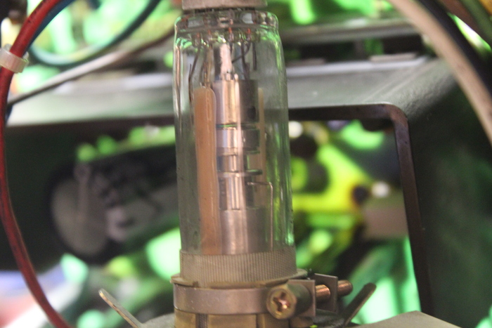
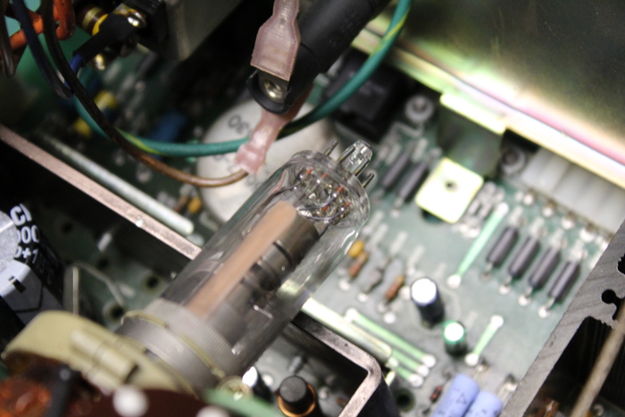
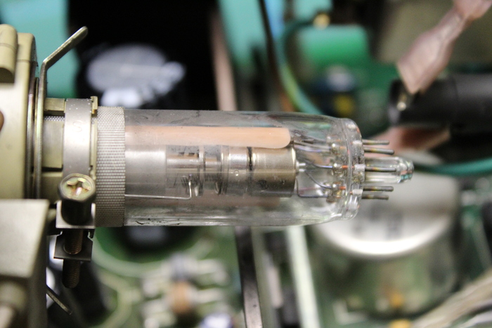
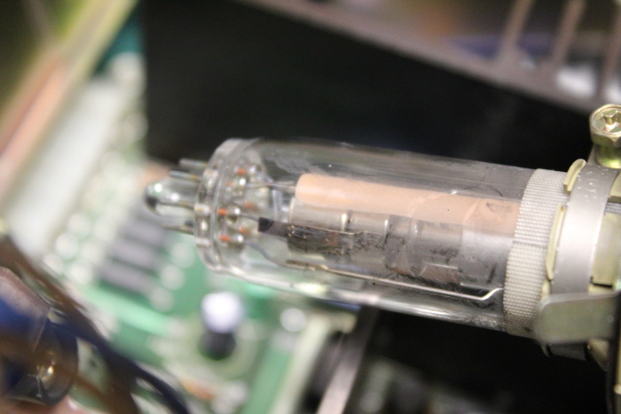
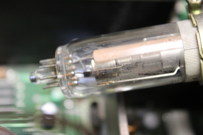
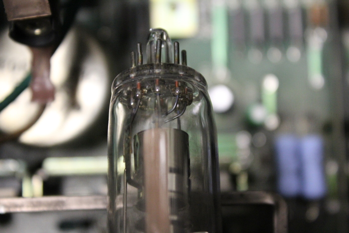
Since disconnecting the CRT prevents the terminal from hiccuping, perhaps there is a short from the heater to the cathode? My tests with the multimeter don't support this though. Anyway, here are some photos of the CRT heater, cathode and focus/accelerating anode assembly. Not too interesting I guess.
—
<2020-04-12 Sun 23:07> SAD NEWS
I wanted to probe about a bit with the flyback, Q202 and CRT all hooked up. Q202 was successfully driving the flyback, but that's as far as I got before smoke started leaking from somewhere. I think that somewhere was the flyback transformer. I'm incredibly disappointed about this, but having explored basically every other option, I think it may be that the primary winding has some shorts.
Tomorrow I will remove the FBT again. I will test the inductance of the primary winding. If it's any lower than before (5.6uH) then I guess we have our answer.
I guess I'll go to bed mopey tonight.
<2020-04-13 Mon 20:17> The crack
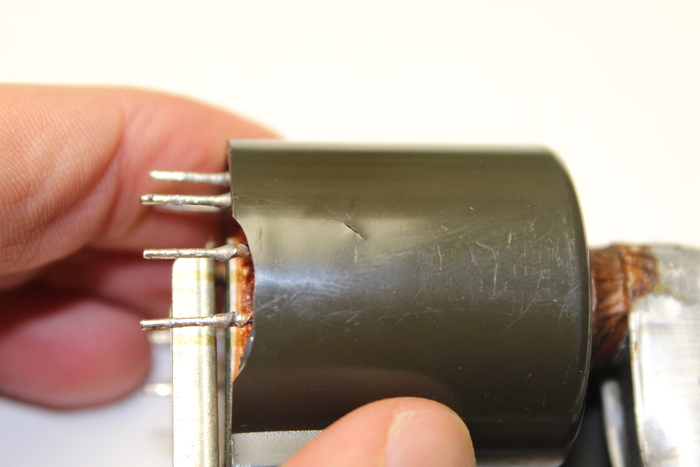
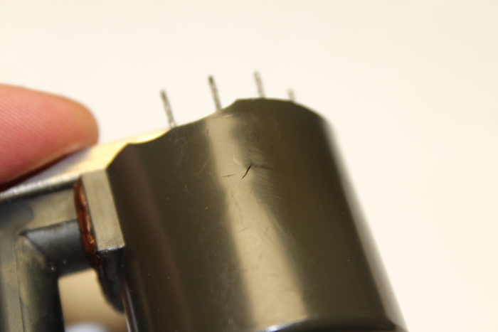
Here are some photos of the crack. It's on the side of the primary. The inductance of the primary has increased, which I find confusing. If some windings had shorted, there would be fewer windings and the inductance would decrease.
Related posts:

Wanting to leave a comment?
Comments and feedback are welcome by email (aaron@nospam-aaronsplace.co.uk).